Inside a Reactor You Can’t Open: CFD Simulation for Trickle-Bed Chemical Reactors
Chemical reactors are among the most process-critical pieces of equipment in the chemical industry and among the least observable. Conditions inside an operating trickle-bed reactor routinely reach temperatures of 160°C or more, with pressures in some configurations exceeding 50 bar. The catalyst bed is packed and opaque. The fluid dynamics of gas and liquid flowing simultaneously through a porous medium are extraordinarily complex. And a design decision you can’t validate until the reactor is built and running is an expensive mistake to make.
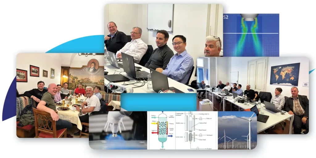
This is the challenge that COA-CFD and its partner Biosimo AG are tackling together using Computational Fluid Dynamics simulation to model what no experiment can easily observe.
The Reactor and the Chemistry
Biosimo AG is developing a sustainable chemical process to produce acetic acid from bio-based ethanol, a ‘drop-in’ chemical that meets industry specifications for direct replacement of fossil-derived equivalents, at an estimated 20% cost reduction. The process uses a trickle-bed reactor: a vertical vessel packed with a heterogeneous catalyst through which gas (oxygen) and liquid (ethanol) flow simultaneously in parallel downward flow.
The reaction is exothermic. Heat management is critical. Localised hot spots can trigger side reactions that reduce yield and degrade the catalyst. Wetting efficiency of the catalyst particles matters too: dry catalyst does not participate in the reaction, and uneven fluid distribution across the reactor cross-section directly affects conversion rates.
To build a commercial-scale reactor with optimal energy management and yield, Biosimo needs to understand the fluid dynamics inside the vessel before committing to a physical prototype. Building multiple hardware prototypes to explore design space is expensive and time-consuming. Simulation offers a faster, lower-cost path to validated design.
The CFD Challenge: Three Phases, One Simulation
Modelling a trickle-bed reactor in CFD is a demanding problem. Three phases are present simultaneously: gas, liquid, and solid catalyst. The porous bed spans the full length of the reactor, requiring either a direct geometric representation of thousands of individual catalyst particles or an effective continuum model of the porosity. The density contrast between gas and liquid phases is large, creating numerical stability challenges. And the chemical kinetics nine candidate models were developed and validated during the first year of the project must be coupled to the fluid dynamics to correctly represent the composition changes, heat release, and mass transfer occurring within the reactor.
It is impossible to build a robust flow dynamic model without a strong and effective representation of the chemical reaction. The reaction changes the composition, and therefore the physical and flow properties, of everything flowing through the reactor.
The COA-CFD team at Engineering Software Steyr (ESS) has approached this progressively:
Initial simulations used an effective porosity model treating the catalyst bed as a continuous porous medium rather than resolving individual particles to represent gas flow through the reactor
A subsequent approach used Lattice Boltzmann Method (LBM) with direct geometric modelling of the porous structure, which performed well for single-phase flow
Current work is exploring Lagrangian Differential Dynamics (LDD), treating gas as a passive background field and directly modelling the liquid phase addressing the challenge of simulating the two-phase system across the required density range
What the Simulation Will Deliver
The target workflow, currently in preparation, will allow reactor engineers to:
Define porous bed geometry by specifying sphere diameter and packing fraction (automatically meshed by script)
Set up tank geometry and inlet conditions
Run liquid flow through the porous bed and extract contact time, the key metric for estimating wetting efficiency and reactor performance
Model chemical reactions and heat transfer within the same simulation framework
Output data will include fluid distribution maps across the reactor cross-section, temperature profiles (essential for hot spot identification and heat management design), wetting efficiency estimates, and ultimately conversion rate predictions. The simulation will also be able to confirm whether heat generated by the exothermic reaction can serve as a feedstock pre-heater a circular energy recovery mechanism that improves overall process efficiency.
Why This Matters for Chemical Engineering
Trickle-bed reactors are widely used in the chemical and petrochemical industries for hydrogenation, oxidation, hydrodesulfurisation, and a range of catalytic processes. The CFD modelling framework being developed within COA-CFD is not specific to the Biosimo process: it is designed to be generalisable to other reactor geometries, chemistries, and operating conditions.
The target users are engineers and plant operators designing or evaluating reactor systems particularly in speciality chemicals, pharmaceutical intermediates, and emerging bio-based processes where physical prototyping is costly and the design space is large. The COA-CFD platform provides cloud-based access to this capability without requiring in-house HPC infrastructure or specialist CFD code development.
Reactors that can’t easily be opened, observed, or probed can now be understood from the inside through simulation before the first weld is made.
The collaboration between Biosimo AG and ESS continues through the final phase of the project, with validation simulations underway and alignment ongoing on experimental data for model verification.
Where Should You Build Your Wind Farm? CFD Simulation Has the Answer.
Choosing the wrong location for a wind turbine can mean years of underperformance, increased mechanical stress, and costly maintenance. Wind energy developers have long relied on weather station data and general meteorological models to make these decisions. But real terrain is complex as mountain ranges, ridgelines, and valley channels create turbulence patterns that no average wind dataset can capture.
COA-CFD is changing that. Through cloud-based Computational Fluid Dynamics (CFD) simulation, wind farm planners can now model the precise airflow across an entire mountain range.
The Problem With Guessing
Traditional wind farm siting relies on long-period wind measurement data gathered from meteorological masts. Engineers extrapolate from that data to estimate average wind speeds and dominant directions at candidate turbine sites. The approach works reasonably well in flat terrain. In complex, mountainous landscapes, it falls short.
What’s missing is turbulence intensity that dictates fatigue loads on turbine blades, reduces energy yield, and shortens equipment lifespan. Turbulence in complex terrain is generated locally by the shape of the land itself: a ridge creates an acceleration zone on its windward face, a valley funnels air in ways no point measurement captures. Siting decisions made without this information are, at best, educated guesses.
Developers planning wind farms in mountainous regions are essentially making multi-million-euro decisions without a complete picture of the wind environment they’re building into.
What COA-CFD Simulates
The COA-CFD wind farm module performs high-resolution simulations of atmospheric boundary layer flow across complex topography. The simulation domain in current validation cases spans 10 km × 10 km with a vertical extent of 4 km, capturing the full landscape a wind farm would occupy.
The workflow is designed to accept real-world inputs from the user:
Terrain topology, converted into a 3D domain geometry (STL format)
Long-period wind speed measurement data from the project site
Surface roughness parameters adjustable to reflect land cover (forest, open field, built-up areas)
Wind direction data covering the full directional spectrum (16 sectors)
These inputs are combined into a time-varying boundary condition applied across the north, east, south, and west boundaries of the simulation domain. The solver then calculates how the wind evolves as it moves across the terrain.
What You Get as Output
The simulation delivers a spatially resolved picture of the wind environment at every point across the candidate site:
Local wind speed at each simulated time step
Average wind speed over the full measurement period mapped across the entire domain
Turbulence intensity fields (critical metric for identifying high-stress zones and optimal placement locations)
The result is a map that tells you, with physical rigor, where wind conditions are most favorable for turbine placement and where elevated turbulence makes siting inadvisable.
This is a physics-based simulation of the actual wind field, derived from real topography and real measurement data.
Who Is This For?
The primary users of this module are organisations in the early planning stages of wind farm development such as developers, energy consultants, and engineering firms working in complex terrain. The tool is particularly relevant for:
Projects in alpine or hilly regions where conventional siting methods are unreliable
Sites where only limited measurement infrastructure exists
Feasibility studies where rapid, cloud-accessible simulation can accelerate the decision process
Because COA-CFD runs in the cloud, the full simulation capability is accessible without on-premise HPC infrastructure or specialist CFD expertise. The platform is designed to be usable by engineers who understand wind energy, not only by CFD specialists.
Part of a Broader Vision
The wind farm simulation module is one application within the broader COA-CFD cloud platform, developed by an international consortium of partners under the CELTIC-Next programme. The project’s mission is the democratisation of CFD simulation, making physics-based engineering analysis accessible to SMEs and industrial users who previously lacked access to this level of capability.
In future versions of the platform, the wind farm module is planned to include a full graphical user interface, making the complete workflow from terrain upload to turbulence map output operable without any command-line interaction.
COA-CFD Mid Term Consortium Review
The COA-CFD project has reached its mid-term review, marking significant progress in making computational fluid dynamics (CFD) more accessible to industries, particularly small and medium enterprises (SMEs). By developing cloud-based, on-demand CFD tools, the project is bridging the gap for companies that traditionally lack the resources for such advanced simulations. The cloud platform alsim Cloud allows users to perform simulations without requiring expensive local hardware, offering an affordable and scalable solution that caters to the specific needs of smaller companies.
A key highlight of the project has been the development of hybrid solvers. These solvers combine multiple numerical methods enabling simulations of complex, multi-physical processes like fluid-structure interaction and electrostatic effects. Optimized for high-performance computing, these solvers utilize GPU acceleration to handle large-scale industrial simulations efficiently. <Read more here>
One prominent application of these solvers is in the automotive industry, where they are being used for top coating simulations. ESS, Audi, and Mazlite are collaborating to simulate the final layer of vehicle painting, a challenging process involving airflow, atomization, and electrostatics. The solvers aim to improve painting quality, reduce material waste, and ensure efficient energy use. This application demonstrates the project’s ability to address real-world industrial challenges.
Additionally, the project has expanded to other use cases, including CFD for chemical reactors in collaboration with Biosimo AG and renewable wind energy simulations with a Korean consortium. These diverse applications showcase the flexibility of the hybrid solvers and their ability to tackle complex scenarios across multiple industries.
Moving forward, the COA-CFD project will focus on validating these tools in real-world settings and optimizing their performance. The cloud-based platform and solver advancements are designed to streamline workflows and reduce costs, ensuring that CFD technologies can be easily adopted by industries that stand to benefit the most. As the project progresses, it continues to push the boundaries of what CFD can achieve, making advanced simulations a practical and accessible tool for innovation across sectors.
Hybridization: Making highly complex solutions accessible for SMEs
CFD simulations often require expertise and costly infrastructure, that’s out of reach for many small and medium enterprises (SMEs) – creating a handicap for them in competing with larger companies.
One of the primary goals of COA-CFD has been – increasing the accessibility of CFD technology for SMEs in design-heavy industries. And a crucial factor that discourages SMEs from using CFD tools is the complexity of its usage.
For certain industrial processes where, complex multi-physics is involved, it becomes impossible to solve problems using a single approach – which demands coupling of different methods. This process, called hybridization, is crucial for COA-CFD as we democratize solutions that are otherwise usable only by experts of the domain.
Process behind hybridization
Hybridizing multiple solvers isn’t straightforward—it involves addressing complex interdependencies between physical quantities such as mass, forces, temperature, and electrostatic potential, among others. For example, Top coating – one of the use cases in COA-CFD – needs to accurately calculate forces on a paint droplet, that are constantly dependent on gravity, air drag and electrostatic forces. A deep understanding of the top coating process, fluid mechanics, electrostatics, and careful modelling was essential to calculate these forces accurately, and then integrate the droplet trajectory. Furthermore, to check for errors, multiple rounds of testing and validation is conducted using real-world data from automotive OEMs.
Computational challenge
One of the biggest challenges in hybridized solvers is the computational cost. The COA-CFD project leverages cutting-edge technology like multi-GPU setups and parallel processing to handle these complex computations efficiently. By decomposing tasks and distributing them across multiple GPUs, we have dramatically reduced computation times without compromising accuracy. This further helps in offering cloud-based online access.
Milestone: Top coating simulation
The completion of our Top Coating solution is a key milestone achievement in the COA-CFD project. This milestone demonstrates the successful hybridization of four different solvers— Lattice Boltzmann Method (LBM), Finite Difference Method (FDM), Lagrangian Particle Method, and Thin Film Solver—into a single, cohesive framework. This solution not only accurately captures the real-world physics of top coating but also sets the stage for applying similar techniques to other industrial processes, like powder coating, and spray waxing.
Top Coating Simulation using hybrid solvers by ess PaintShop.
Conclusion
As we continue to develop the COA-CFD platform, we will keep refining our hybridization techniques to ensure even more accurate and faster simulations for complex industrial applications. The democratization of CFD software remains at the heart of our efforts, ensuring that users across various industries can easily implement and benefit from cutting-edge fluid dynamics simulations. Stay tuned for further updates!
In a significant stride towards fostering innovation and pushing the boundaries of technology, we are thrilled to announce the addition of several esteemed firms to our consortium. This expansion marks a new chapter in our journey, one that promises to bring fresh perspectives, groundbreaking ideas, and a shared commitment to excellence in the fields of automotive engineering, chemical processing, and renewable energy solutions. We warmly welcome Biosimo, Mazlite, Soda System, Dtonic Corporation, Institute for Advanced Engineering, Dohwa Engineering Co., and Unison to our collaborative network. Their expertise and innovative spirit are invaluable assets to our mission of driving technological advancements and sustainable solutions.
Biosimowill cooperate to build a software modules for CFD simulation in trickle bed chemical reactors. The main physics in the reactor includes chemical reaction, heat convection and transfer, conjugated heat transfer, pore flow through granular catalyst, and material convection and diffusion.
Mazliteprovide further insides into the top coating case with their novel technology to anlyse pictures.
All Koreans partners Soda System, Dtonic Corporation, Institue for Advanced Engineering, Dohwa Engineering Co. and Unison support to build CFD solutions for renewable energy productions in the area of wind turbines and water management. For wind turbine, the aim of the work is to develop a simulation software to assess the efficiency of wind turbine under various geological conditions, and to help selecting the optimal construction sites for turbines.
As we welcome our new partners to the consortium, we look forward to the innovative solutions and advancements that our collaboration will bring to the forefront of technology and sustainability. Together, we are not just aiming for incremental improvements; we are striving to redefine what is possible, making a tangible impact on the industries we serve and the world at large. Here’s to a future filled with collaboration, innovation, and success.
Manage Consent
To provide the best experiences, we use technologies like cookies to store and/or access device information. Consenting to these technologies will allow us to process data such as browsing behavior or unique IDs on this site. Not consenting or withdrawing consent, may adversely affect certain features and functions.
Functional
Always active
The technical storage or access is strictly necessary for the legitimate purpose of enabling the use of a specific service explicitly requested by the subscriber or user, or for the sole purpose of carrying out the transmission of a communication over an electronic communications network.
Preferences
The technical storage or access is necessary for the legitimate purpose of storing preferences that are not requested by the subscriber or user.
Statistics
The technical storage or access that is used exclusively for statistical purposes.The technical storage or access that is used exclusively for anonymous statistical purposes. Without a subpoena, voluntary compliance on the part of your Internet Service Provider, or additional records from a third party, information stored or retrieved for this purpose alone cannot usually be used to identify you.
Marketing
The technical storage or access is required to create user profiles to send advertising, or to track the user on a website or across several websites for similar marketing purposes.